


Compatible: (4.2L)
2012 - 2015 Audi RS4
2010 - 2015 Audi SRS5
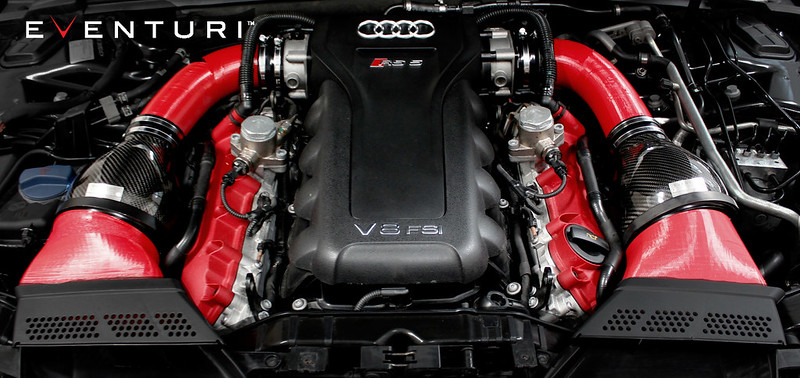
The Audi RS5/RS4 Eventuri intake was developed after consultation and support from RS5 enthusiasts. We have completely re-engineered the inlet track from the ducts to the filters and the inlet tubes. The restrictive stock airboxes and duct feeds have been replaced with a highly efficient – fully sealed system with smooth transitions to allow the airflow to remain full and laminar. The resulting performance gains, sound and aesthetics are industry leading for this platform.
The Eventuri Difference
The RS5/RS4 Eventuri system uses our Patent Pending Carbon fibre Housings which provide an aerodynamically efficient airflow path from the filters to the throttle bodies. Not just another cone filter with a heat shield but a unique design which invokes the Venturi affect.
With so many aftermarket intakes available, the natural question arises:
“So what’s so special about the Eventuri Intakes?”
There are two main elements in explaining the answer to what sets us apart from the rest:
The Patented Eventuri Filter Housing
Even at first glance the Eventuri intake looks very different to many other aftermarket intakes. Unlike the majority of intakes, which use the same cone filter/tube/heat shield configuration, the Eventuri design is fundamentally different and has been Patented.
AFTERMARKET INTAKE SYSTEMS
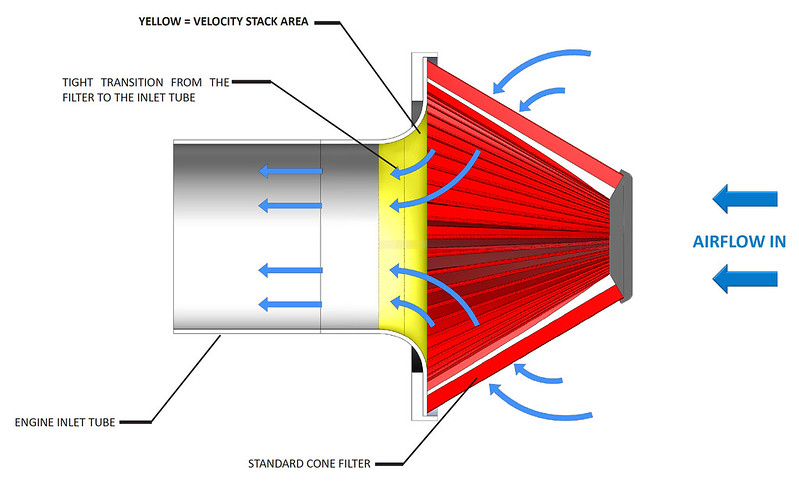
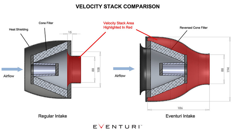
Most aftermarket intakes use a cone filter mated to an inlet tube with some type of heat shielding. In this configuration airflow must negotiate a path from the large diameter at the base of the filter through to the smaller diameter of the inlet tube in a relatively short distance. There is usually a velocity stack at the base of the filter to help with the transition, however the stack is usually small. This sudden transition in geometry is detrimental for flow. The result is a loss of throttle response and performance gains are usually limited over the OEM intake system. The diagram below shows a typical aftermarket intake using a cone filter secured to an engine inlet tube. The filter uses a standard velocity stack, which has been highlighted in yellow.
THE EVENTURI INTAKE SYSTEM
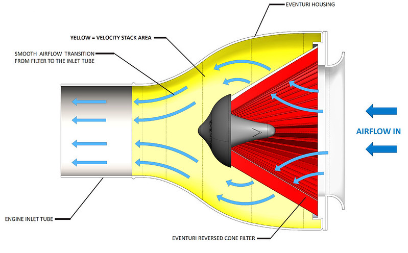
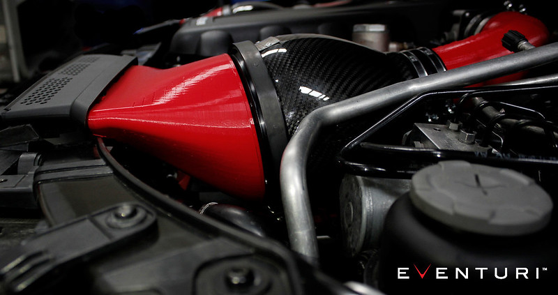
The Eventuri is a new type of intake design, which has been granted a patent. We use a cone filter – but here it is inverted and decoupled from the inlet tube. By removing the direct connection between the filter and the inlet tube, the filter is no longer dictating the shape of the airflow. This is now being done by the carbon housing, which is designed to smoothly guide the air into the inlet tube without a sudden change in geometry. This means that we keep laminar conditions throughout the intake, which is a lot more efficient. Furthermore, the funnel-shaped housing invokes the Venturi effect where the smooth reduction in cross-sectional area along the length of the housing causes the airflow to increase in velocity. Essentially the entire housing acts as a large velocity stack. On the road this translates to more power with a smoother delivery as well as sharper throttle response since the airflow is not inhibited by abrupt geometry changes andso is more likely to remain laminar. The diagram below shows an Eventuri intake system using a reverse mounted filter inside an Eventuri housing. The large velocity stack area is highlighted in yellow.
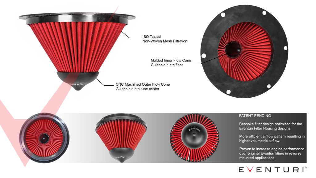
Eventuri Bespoke Filters
To compliment our unique filter housings we designed our filters specifically for this reverse mounted configuration in order to provide the optimum airflow through the system.
The Complete Solution
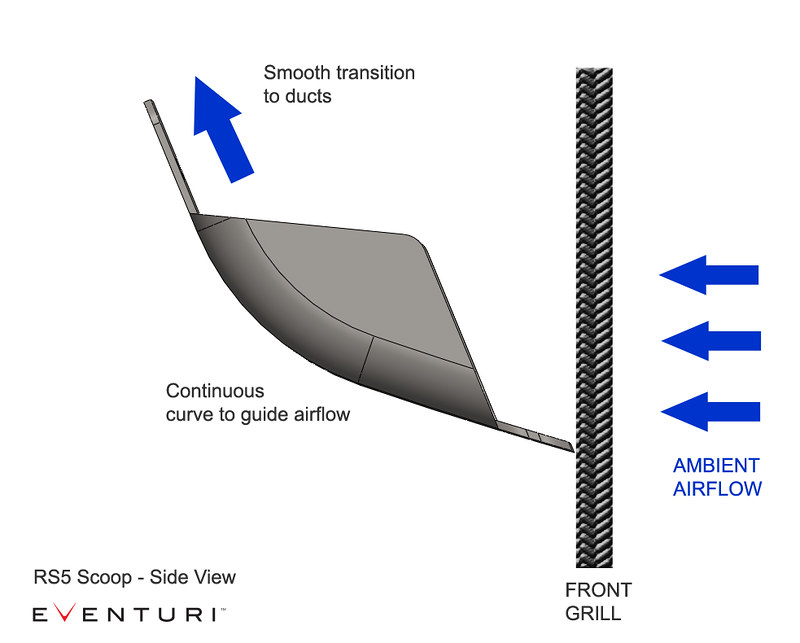
The final element to our design – which is as important, is our emphasis on creating a complete solution. We dedicate a lot of design effort on ensuring the filter housings are provided with ambient air in the most efficient way possible. Allowing the filters to draw in heated air from the engine bay defeats the objective and in many cases is the cause of an actual loss in power over the stock system once the engine bay is heat soaked. Simply using heat shields is not enough – there must also be a method of channeling cold air into the intake. This is where we have seen some companies use “scoops” but on closer inspection are usually very flat and almost perpendicular to the oncoming air. Not the ideal solution for trying to redirect air at high speeds! Our scoop designs have, where possible a curved face for as much of the exposed area as possible in order to smoothly redirect incoming air to the filters. In doing so we ensure that engine bay heat is displaced and so intake air temperatures are kept as low as possible.
From scoop to duct to housing to inlet tubing – by utilizing organic shapes, we invest a great deal of time and effort in providing a smooth path for the airflow to follow. Hence ensuring maximum efficiency of the system.
Below is an independent dyno graph showing the comparison between the Eventuri and the stock airboxes on a standard RS5. As you can see, power is increased through a large portion of the rpm range not just at the peak. This translates on the road to increased part throttle and full throttle response with the car pulling much more eagerly to the redline. The testing was done on the same day back-to-back and temperatures were monitored to ensure consistency. The car was tested firstly with the stock intake - hood closed. We then left the car on the dyno and installed the Eventuri. The car was then run again - hood closed. Several runs were carried out with both configurations to get a consistent result. Since dyno figures vary between runs - for fairness we chose to publish figures using the highest stock run VS highest Eventuri run. Here you can see the 2 best runs with both configurations.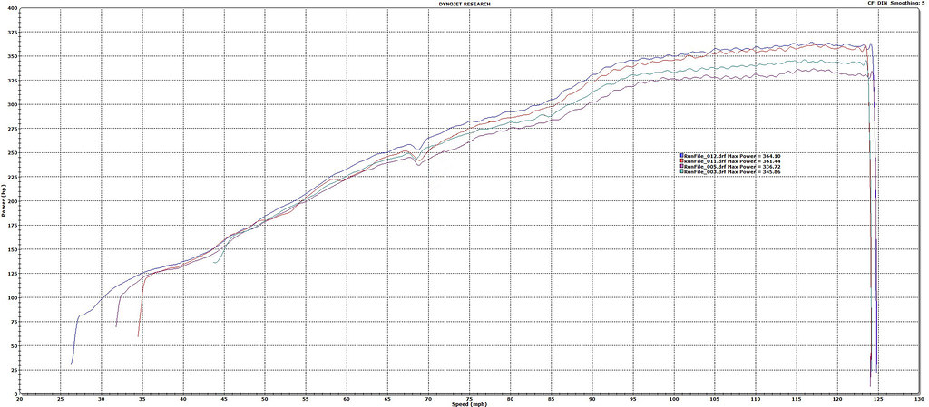
We could have shown the highest figure achieved with the Eventuri VS the lowest achieved with the stock setup, however this would not be a fair comparison. Just to illustrate the variation, here is the graph showing highest Eventuri VS lowest stock which was recorded on the day showing a gain of over 32hp at the wheels.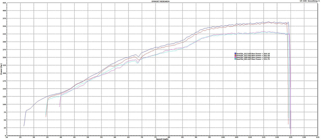
Here is another graph showing the difference between the stock airboxes and the Eventuri intake system - this time on a B8 RS4. Dyno runs were done on the same day and the car remained strapped to the dyno during installation to ensure strap tensions were the same for both tests. Here we can see a considerable gain in both torque and power - with 25ft-lb toque gained in the midrange and 25hp gained before peak rpm.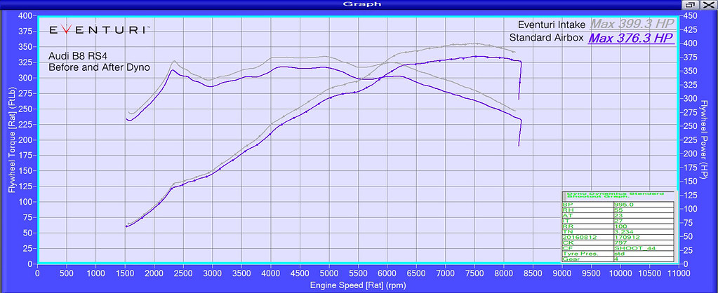


The RS5 Eventuri intake was developed over a number of months with every detail considered. Here you can read about our development process as it happened and the reasoning behind the design decisions we took.
We are redesigning the inlet track to be as aerodynamically efficient as possible in the given space. The standard airboxes are restrictive as they have a small rectangular filter which then has to transition very quickly to a circular tube. It is this transition which causes turbulence and hence increases the drag of the inlet track. Furthermore the ducts feeding the airboxes have deep pleats which again is not good for smooth flow. We will be implementing our Patent Pending Eventuri filter housings to provide a smooth transition from filter to inlet tube.
All carbon components will be made from prepreg carbon fibre for strength and for minimising heat transfer to the airflow.
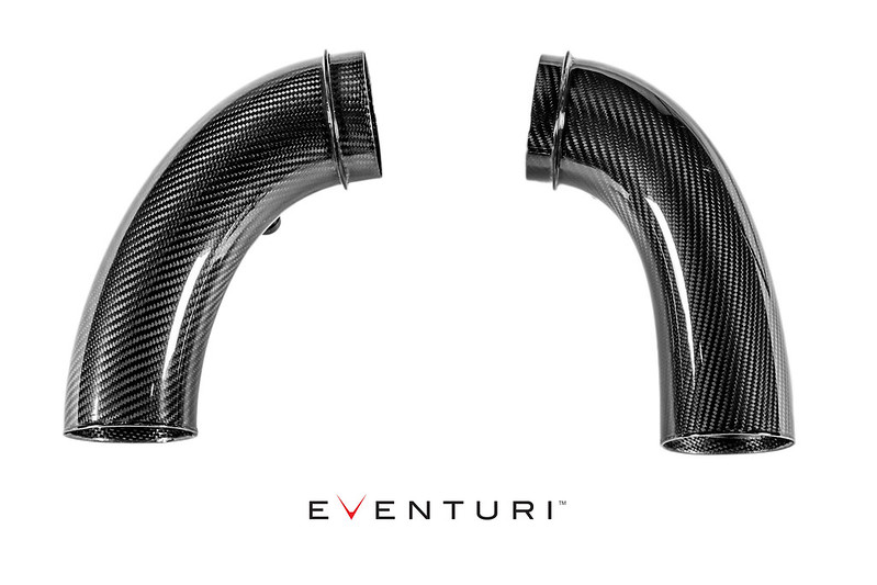
Mated to the Eventuri housing will be a carbon fibre tube which will smoothly run to and match the diameter of the throttle body. We use CF because it is a great insulator across its thickness. Aluminum tubes could be used however this is more than 400 times worse than CF at insulating the intake air from engine bay heat!
Finally in order to feed the filter housing with cold air - we are designing ducts which connect to the OEM front ducts and then smoothly transitions to the mouth of the housing. To further improve the cold air feed we are designing extensions for the stock intake ducting behind the grill to act like scoops. Since the filter housing will be rigidly mounted to the engine via the carbon tube, we won't be attaching the housing to this duct - there needs to be some flexibility in the system so we are working on a floating type mount where the duct will simply nest the housing allowing some movement.
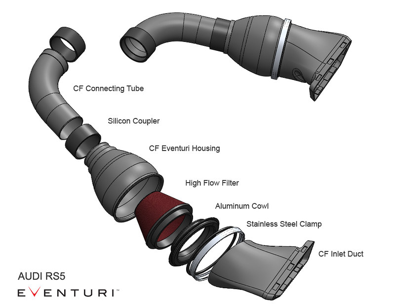
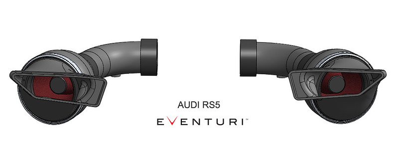
Here are some CAD images of the system currently in development (scoop extensions not shown yet):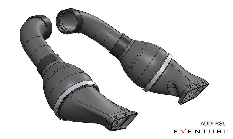
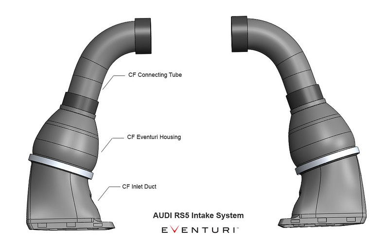
Here are the first 3D printed parts in place - clearly the space is very restricted so we are optimising the filter housing for maximum volume in the given envelope.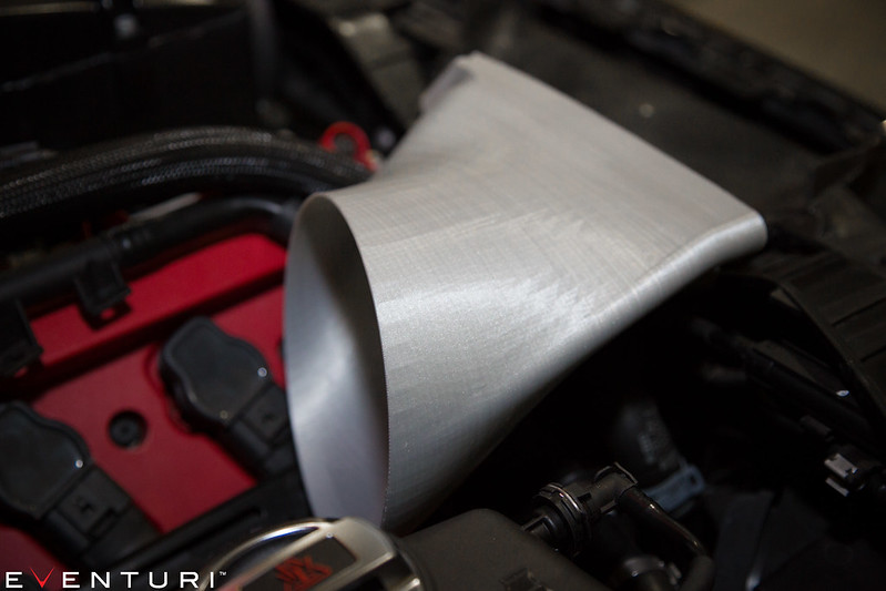
Update:
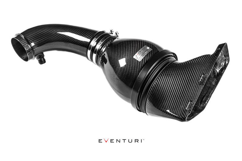
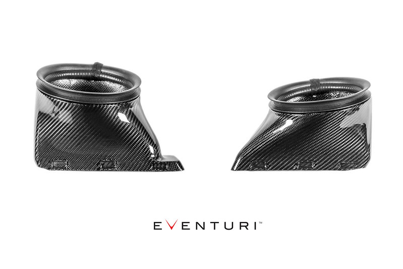
After a number of iterations we have finalised the filter housing shape and size. It fits neatly in the engine bay yet has sufficient volume and length to allow the airflow to transition smoothly to the intake tubes for the throttle bodies. Here are the prepreg carbon housings: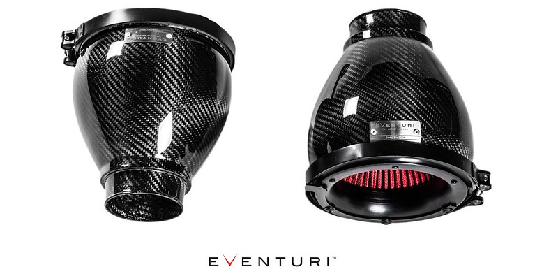
Update:
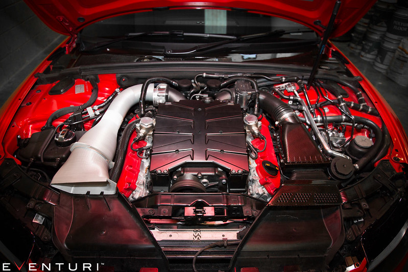
We finished the left hand side (as you look at the engine) and finalised the way in which the intake housing mates to the duct to allow engine movement. Basically the carbon tube and housing will be mounted to the engine and so will move with the engine - the duct which is attached to the stock ducting will not be attached to the housing but rather will have a rubber extrusion sealing against the filter housing. This allows movement and also ensures no hot air is drawn in by the filters.
The right hand side is almost finalised now - there is less space here due to the aircon pipes and so we had to spend some time getting the angles right. Here are some photos with the carbon housings and 3D printed tubes and ducts in place: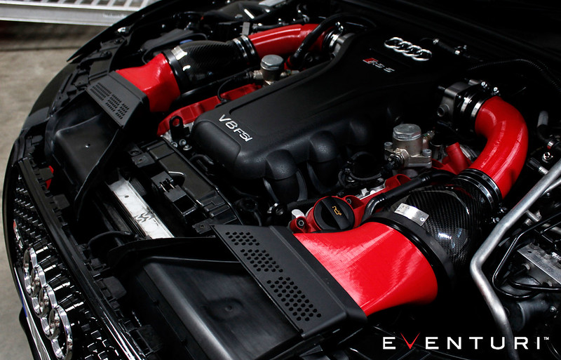
The final pieces are the scoops which will protrude from the stock ducting into the front grill. We have seen other attempts at making scoops and they are simply too flat for effective channeling of air into the ducts. Our scoops have been designed with a continuous curve so that the oncoming air meets a curve and is forced into the duct rather than meeting a flat surface and causing turbulence.
The scoops will protrude right up to the grill and so will be visible from outside - as these will be carbon, they will provide a nice visual touch - hinting at what is under the hood.
Here are the CAD images of the scoops under development: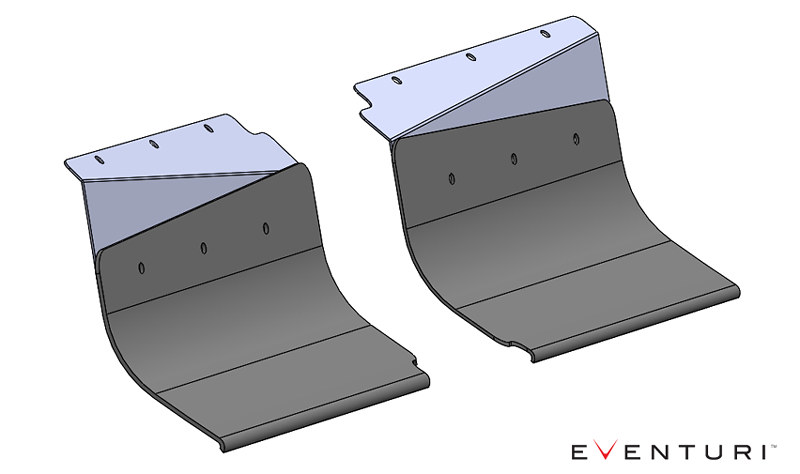
CFD and CAD
The CFD simulations show the airflow characteristics through one side. You can see that the flow is smooth with minimal turbulence - importantly through the tubes, the flow is full and steady. The velocity of the airflow is shown by colour - blue is slowest and red fastest. There is a steady increase in velocity through the system as the cross sectional area reduces smoothly which is as expected and it all bodes well so far for the real test!
CFD:
CAD:
Update
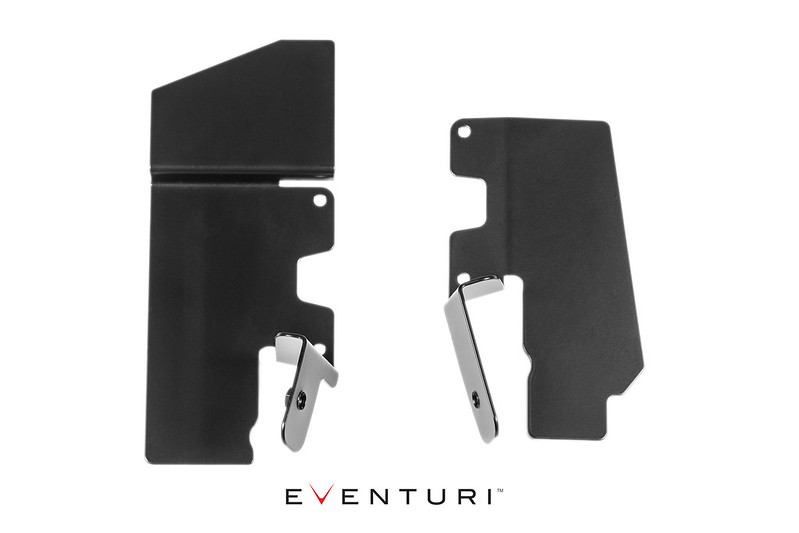
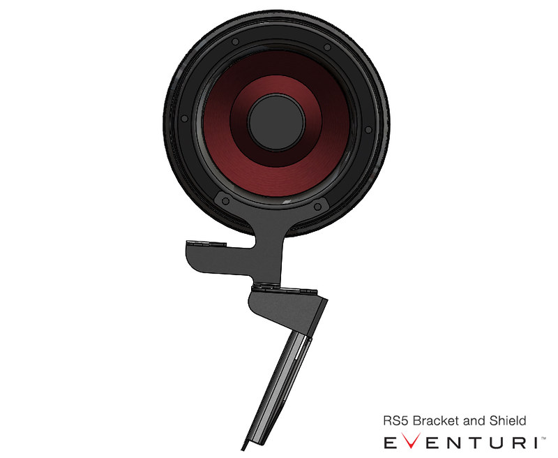
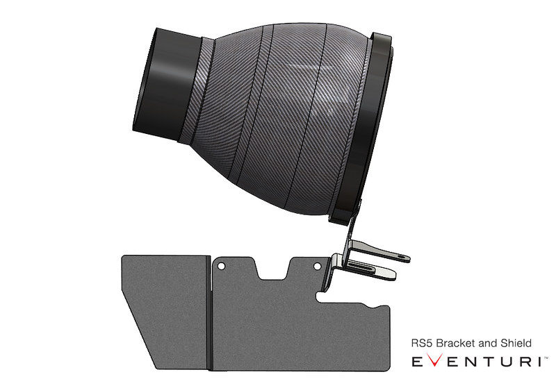
The carbon tubes and filter housings will be mounted to the engine by using the studs which currently hold the OEM bracket for the airbox.
There are 2 brackets - one mounted to the housing directly and then the other mounted to the engine. Since the exhaust manifolds are exposed in the airbox area - we designed the engine bracket to extend and cover the manifolds to minimise direct radiant heat transfer.
The carbon intake tube and housing will move with the engine - the carbon duct is mounted to the OEM front ducting and is connected to the housing by a rubber seal - so allows for movement as it isn't rigidly mounted to the housing.
All brackets will be laser cut from stainless steel and then powder coated to improve appearance and heat insulation properties.
Some CAD images: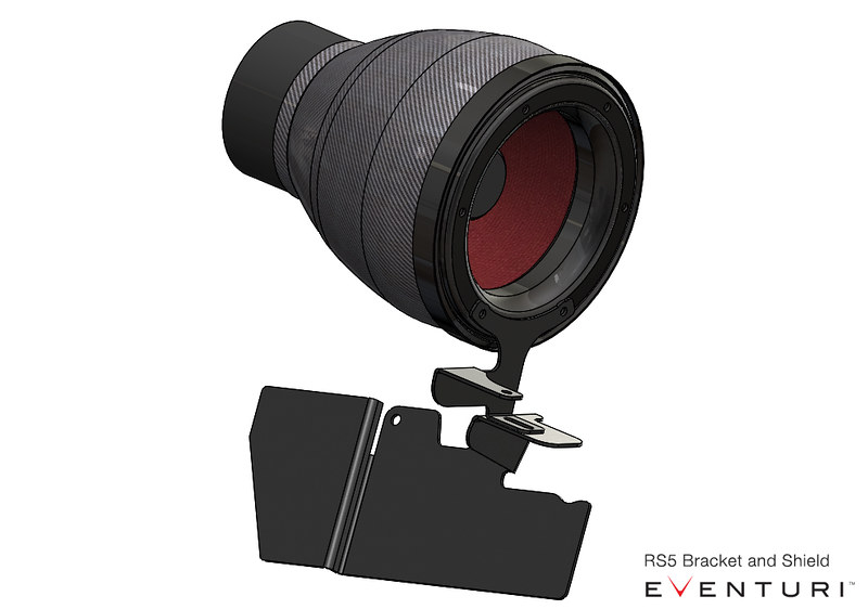
Install Guide:


Warranty:
![]()