Compatible: (Type 42)
2006 - 2015 Audi R8
***This is a chassis mount wing. Comes with Carbon Fiber Trunk Replacement***
Spanning 71" inches, the GTC-500 Carbon Fiber Adjustable Wing is the largest wing available in APR's catalog. With its optimized 3D airfoil shape, the GTC-500 is perfect for high speed touring applications and supplies an ample amount of downforce without causing excess drag. All GTC Series wings feature an aerodynamic 3D designed airfoil shape to obtain the optimal balance of downforce. This design allows for a reduction in drag, yet maintains an ideal level of downforce. Computational Fluid Dynamics (CFD) analysis was performed on this wing to support validation of its aerodynamic design.
Each GTC Series airfoil is composed of lightweight and durable carbon fiber reinforced polymer (CFRP) composite materials. These airfoils contain pre-pregnated woven carbon fiber sheets for superior strength and low weight. All CFRP airfoils are made using pre-pregnated composite manufacturing processes (i.e. high-temperature autoclave and vacuum bagging) in high-quality aluminum billet molds.
Supporting the airfoils are 10mm "aircraft grade" 6061 billet aluminum pedestals that come in a flat black powder coat finish.
Note: Mounting bases sit at edges of trunk lid
Airfoils (a.k.a. "wings")
What is an airfoil, and how does it work:
An airfoil is a body (such as an airplane wing or helicopter blade) designed to provide a desired reaction force when in motion relative to the surrounding air.
There has been much discussion with regards to how and why airfoils really work. The popularly-known explanation (as seen in K-6 textbooks) involves mis-applying Bernoulli’s principle by stating that high-pressure, low-velocity air on the bottom-side of the airfoil and low-pressure, high-velocity air on the top-side, which recombines at the trailing edge of the airfoil at the same time, regardless of angle-of-attack, is the sole mechanism by which lift is generated.
Well, if this is the case, then we would have a really, really tough time trying to explain how airplanes fly upside down: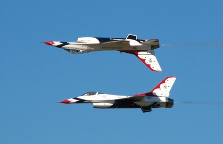
The truth is, the top-side air travels significantly faster than the bottom-side air. They never recombine (the image below illustrates this fact). 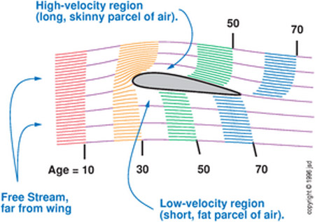 (Velocity field around a wing, image from http://www.av8n.com)
Additionally, the image below illustrates, using pressure patterns, that the angle-of-attack indeed has profound effects on the lift that's generated. 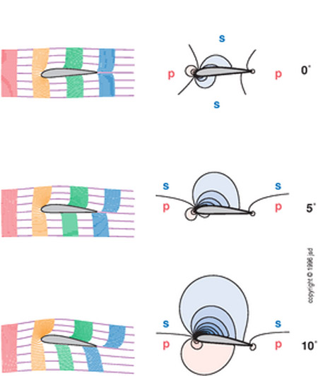 (Pressure patterns at different angle-of-attacks (red shaded regions indicate positive pressure relative to atmosphere, blue shaded regions indicate negative pressure relative to atmosphere, image from http://www.av8n.com)
Besides using Bernoulli’s principles (which accounts for conservation of energy), Newton’s principles (conservation of momentum), Euler’s equations (conservation of mass, momentum, and energy), and Navier-Stokes equations (all of the above plus viscosity) must also be dealt with in order to fully understand the generation of lift.
A good article that provides a good, brief introduction to these principles is available on NASA’s website here:
http://www.grc.nasa.gov/WWW/K-12/airplane/bernnew.html
For more detailed, technical explanations regarding lift, please visit the following websites:
“A Physical Description of Flight,” by David Anderson & Scott Eberhardt
http://home.comcast.net/~clipper-108/lift.htm
“Airfoil Lifting Force Misconception Widespread in K-6 Textbooks,” by William Beaty, 1997
http://amasci.com/wing/airfoil.html
“How do wings work?” by Holger Babinsky, 2003
http://www.iop.org/EJ/abstract/0031-9120/38/6/001
"Why aircraft fly,” by David Auerbach, 2000
http://www.iop.org/EJ/abstract/0143-0807/21/4/302
Why put airfoils on cars:
Airfoils, when properly mounted at the rear-end of a race car, can generate large amounts of downforce. This downforce offsets the aerodynamic lift inherent to the car, and in turn increases the amount of tire grip available. This increased tire grip allows the car to carry higher speeds through the corners and out of corner exits. Being able to carry the greatest corner exit speeds is critical to producing the lowest lap times, especially when there are many corners that lead to long straightaways.
What to consider when putting airfoils on cars:
In application (airfoil on a race car), the key point to understand is to know that the amount of lift an airfoil generates is dependent on many things, including (but not limited to):
1. Angle-of-Attack (AOA).
2. Shape.
3. Size.
4. Position in the air stream.
Considerations must be made for all of the above items when designing, installing, and using an airfoil on a race car.
3D airfoils: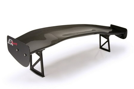 (APR Performance GTC series airfoil)
A 3D airfoil is an airfoil that has variable airfoil cross section across its span. Most modern aircraft airfoils are 3D airfoils. When a 3D airfoil is designed for use on a production-based race car, the outer sections will typically have much more AOA built-in than the center section. For example, if the center section is set to zero degrees (relative to the ground), then the outer sections may end up at 15 degrees angle (relative to the ground).
Why and when to use a 3D airfoil (rather than a 2D airfoil):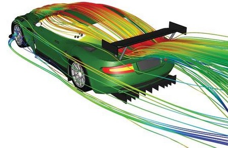 (Computational Fluid Dynamics (CFD) illustration of airflow around Aston Martin race car)
There is a popular notion that, in order for an airfoil to function on a race car, the airfoil needs to be in clean, free-air at or above the rear roofline of the car. This is only a partially-true statement. On cars with solid roofs and sloping rear windows, the air that flows from the rear center edge of the roof will travel downward at an angle toward the airfoil. The problem here is that only the center section of the 2D airfoil will see this downward "push" of air, while the outer section of the 2D airfoil will see much less of this (it will see straighter, freer air).
Decreasing the 2D airfoil's angle-of-attack to accommodate for the downward airflow causes the outer sections to produce relatively less downforce. Increasing the 2D airfoil's angle-of-attack causes the center section to produce relatively more downforce. The 2D airfoil ends up functioning inefficiently in this unbalanced state. This is a situation where the 3D airfoil has an advantage. The 3D airfoil's built-in angle-of-attack variations allow it to function more efficiently when it is mounted below the roofline. When the center section is mounted at 0 degrees angle-of-attack (relative to the ground), it acts as though it has a positive (typically 15 to 20 degrees in a sedan-type car) angle-of-attack relative to the airflow coming from the rear center edge of the roof. The outer sections, with the higher angle-of-attack built-in, are better-suited to take advantage of the cleaner, freer air stream. Therefore, the 3D airfoil, when used in a sedan-type car and mounted below the roofline, is able to function more efficiently (and in a more balanced state) than a 2D airfoil.
Which type of airfoil is better?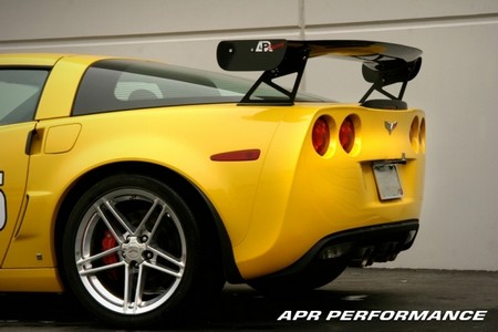 (APR Performance GTC series airfoil for C6 Corvette application)
There is not going to be one simple answer to this question. In reality, a better question to ask may be, "which type of airfoil is better for my application?" In some cases, it may be better to use the 2D airfoil. In other cases, it may be better to use the 3D airfoil.
In order to find the answer, we must know our intended use and we must consider the following:
1. Type of car (sedan, coupe, hatchback, open-wheel, etc.).
2. Approval of the specific airfoil (type, size, supplier, etc.) for the race series.
3. Mounting-height rules for the race series.
Typically, when there is a mounting-height restriction that requires the airfoil to be mounted below the roofline, it will likely be better to use a 3D airfoil. When there is no mounting-height restriction, either a 2D airfoil mounted above the roofline or a 3D airfoil mounted below the roofline may work.
(Dark Horse Racing's 2007 SCCA ITO entry)
Install Guide:
Warranty:


